A Foldback Current Limiting Circuit for Voltage Regulator

A foldback current limiting and voltage stabilizer technology, applied in instruments, regulating electrical variables, control/regulating systems, etc., to achieve the effect of reducing power consumption, size and cost

Active Publication Date: 2017-08-18
NANJING MICRO ONE ELECTRONICS
View PDF6 Cites 0 Cited by
  • Summary
  • Abstract
  • Description
  • Claims
  • Application Information

AI Technical Summary

Problems solved by technology

A major disadvantage of fixed-current-limited power supplies is the need for a transfer tube as a regulating device to discharge current when the output is short-circuited.

Method used

View more

Image

Smart Image Click on the blue labels to locate them in the text.
Viewing Examples
Smart Image
  • A Foldback Current Limiting Circuit for Voltage Regulator
  • A Foldback Current Limiting Circuit for Voltage Regulator
  • A Foldback Current Limiting Circuit for Voltage Regulator

Examples

Experimental program
Comparison scheme
Effect test

Embodiment Construction

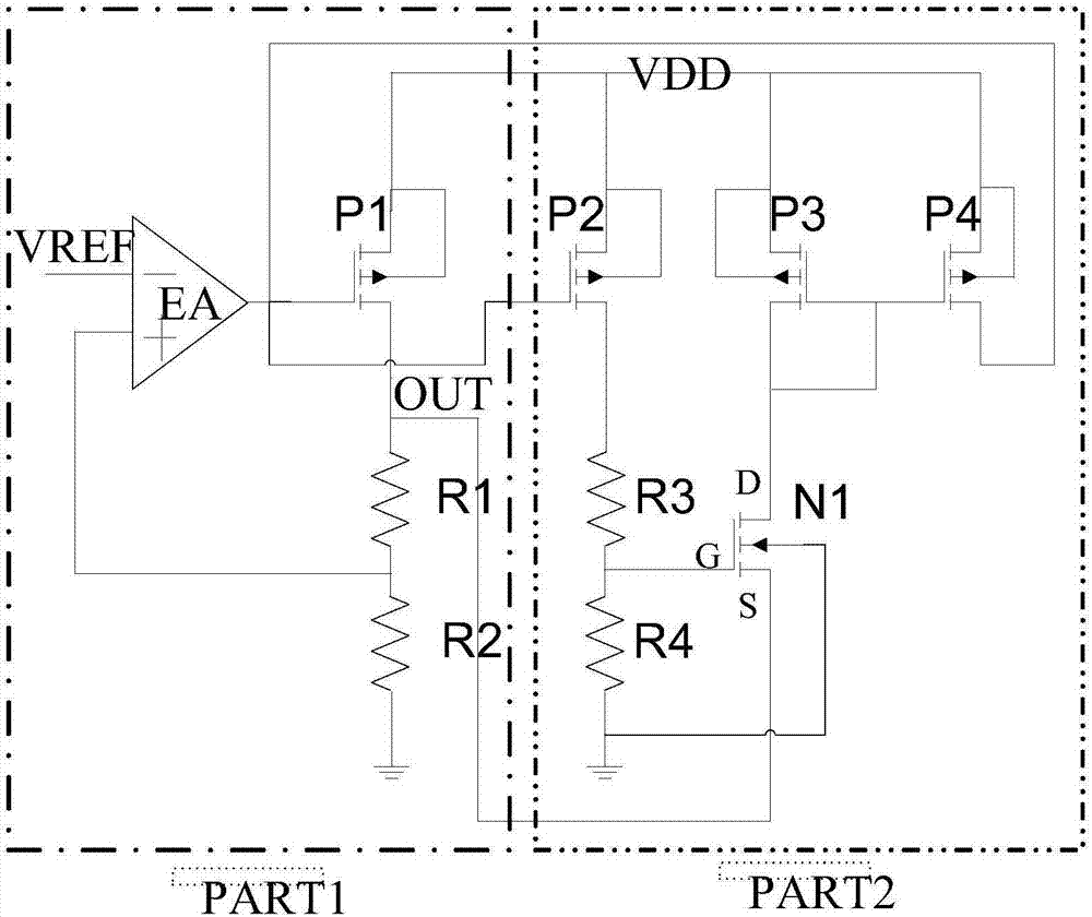
[0013] Depend on figure 1 , PART1 is a traditional linear regulator, including differential amplifier EA, power transmission tube P1, and output voltage resistor feedback network R1 and R2. The input terminals of the differential amplifier EA are divided into positive input and negative input, marked as + and - respectively, wherein the positive input terminal is connected to the connection terminals of R1 and R2, and the negative input terminal is connected to the reference voltage VREF. The output of the differential amplifier EA is connected to the gate of the power transmission transistor P1. The drain of the power transmission transistor P1 is connected to one end of the resistor R1 to provide an output voltage OUT, and the source and substrate of the power transmission transistor P1 are connected to VDD. The other end of the resistor R1 is connected to one end of the resistor R2 and the positive input end of the differential amplifier EA, and the other end of the resist...

Login to view more

PUM

No PUM Login to view more

Abstract

A fold-back current limiting circuit for a voltage stabilizer is connected to the output end of the voltage stabilizer and comprises PMOS transistors P2, P3 and P4, an NMOS transistor N1 and resistors R3 and R4. Source electrodes and substrates of the PMOS transistors P2, P3 and P4 are all connected with a power source VDD, a grid electrode of the PMOS transistor P2 is connected with the output end of a differential amplifier EA in the voltage stabilizer, a drainelectrode of the PMOS transistor P2 is connected with one end of the resistor R3, and the other end of the resistor R3 is connected with one end of the resistor R4 and a grid electrode of the NMOS transistor N1. The other end of the resistor R4 is grounded, a source electrode of the NMOS transistor N1 is connected with the output end OUT of the voltage stabilizer, a drain electrode of the NMOS transistor N1 is connected with a drain electrode and a grid electrode of the PMOS transistor P3, the drain electrode of the NMOS transistor N1 and a grid electrode of the PMOS transistor P4 are connected together, a substrate of the NMOS transistor N1 is grounded, and a drain electrode of the PMOS transistor P4 is connected with the output end of the differential amplifier EA in the voltage stabilizer.

Description

technical field [0001] The invention relates to a voltage stabilized power supply, in particular to a foldback current limit circuit (foldback current limit) for a voltage stabilizer. Background technique [0002] Connecting a voltage regulator to an external low-impedance load at the output can cause an overcurrent condition. In the prior art, a common current control method is fixed current limit. This circuit has an accurately set maximum current limit, which is not affected by load or short circuit conditions. A major disadvantage of fixed-current-limited power supplies is the need for a pass transistor as a regulator to discharge current when the output is shorted. Contents of the invention [0003] The purpose of the present invention is to provide a foldback current limiting circuit for a voltage regulator, which can reduce the output current when the output of the voltage regulator is short-circuited, and provide positive feedback through the voltage drop on the d...

Claims

Login to view more

Application Information

Patent Timeline
no application Login to view more
Patent Type & Authority Patents(China)
IPC IPC(8): G05F1/10
CPCG05F1/10
Inventor 王海波张洪俞
Owner NANJING MICRO ONE ELECTRONICS
Who we serve
  • R&D Engineer
  • R&D Manager
  • IP Professional
Why Eureka
  • Industry Leading Data Capabilities
  • Powerful AI technology
  • Patent DNA Extraction
Social media
Try Eureka
PatSnap group products